MSL G64 device library
 Status:
This documentation applies to version 1.20.80.64 (20/5-2003) of the G64 device library.
 Contents:
- Overview
- G64 Device parameters, standard crates
- G64 Device parameters, CRYSIS crate
- G64 Device Configuration
- CAEN device
- GFD/Timing system overview
- AEG Timer and event decoder device
- GFD device
 Overview:
The MSLG64 Device library originally only contained MSL G64 based devices. Since some G64 crates are controlled through CAMAC, the core code for handling CAMAC access has been implemented in this library. Therefore the library has now evolved and include other CAMAC based devices: CAEN (under development) and timing/GFD system devices (under development).
G64 Devices:
Each MSL G64 device handles a single serial G64 crate. A standard MSL G64 crate can handle up to 16 parameters sets (status word, acquisition data, command word, control data). The configuration of the parameter usage is stored in the database and loaded by the device during initialisation. The device must be stopped and restarted in if the configuration data is changed for the device. Some G64 crates has special functions with none standard interfaces. These have been hard coded into special instances of the device crate type.
The MSL G64 crates are controlled through a serial interface or a CAMAC interface.
The device implementation is based on the same core code as the ISA G64 device - having the same overall structure as the MSL G64. The major difference is the interface and the number of parameters (64 in the ISA version).
Other devices, see
MSL GFD/Timing system overview
G64
Device parameters, Addressing,
Standard crates:
Device status/control parameters:
The device status and control parameters can be accessed by 'One Dim addressing'. Most of the status and control values are common for all G64 crate types.
|
Parameter |
Suggested |
Description |
Data Type |
Interpretation |
Mode |
Comment |
|
0 |
Reset |
Reset the device |
Bit |
Check box with pulse bit dataserver |
Write |
For serial crate devices this operation will close and reinitialise the communication port connection. |
|
1 |
Enable |
Enable/disable the device |
Bit |
Check box. |
Write |
|
|
2 |
ResetCnt |
Resets status counters |
Bit |
Check box with pulse bit dataserver |
Write |
|
|
10 |
Active |
Crate state |
Bit |
Status bit |
Read |
True, when the crate is active and the communication is okay. |
|
100 |
nCommErr |
Number of communication errors |
Double |
|
Read |
Counts the number of communication errors |
|
101 |
nSendCmd |
Number of send commands |
Double |
|
Read |
|
|
102 |
NStatusRd |
Number of status reads |
Double |
|
Read |
|
|
103 |
nResend |
Number of resends |
Double |
|
Read |
Number of resends of commands when error in received data detected. |
|
104 |
lastError |
Last error as a text |
String |
|
Read |
|
G64 crate parameters:
Standard G64 parameters are accessed by one of the 5 G64 address types:
G64 Conversion: Address type used for all floating point parameters defined for the crate.
G64 Bit: Address type used to access a bit.
G64 Word: Address type used to access a word.
G64 Word Filtered: Address type used to access part of a word (selected by a bit mask filter and a rotation number).
G64 Three state word: Special address type used to combine two bits into a three state value.
All of these address types use the first general purpose address fields as
follows:
a0: G64 address
a1: 0: stts (status), 1: stts-data (acquisition), 2: cmd (command), 3: cmd-data
(control)
(Remark: stts: ISA notation, (status) MSL notation. The implementation code
uses the ISA notation.)
When the address type is 'G64 address', the parameters on individual G64 are accessed.
Priority update: Can be set on any parameter by setting A5, bit 0. Parameters with the priority bit set will be updated before other parameters when they are scheduled for update. Used correctly (not to may priority parameters), this will ensure a more live an steady data stream to parameters with priority.
Automatic increase of update rate: When a dac value is set in a given parameter set, the corresponding adc value is updated fast with highest priority for a limited number of readings.
G64 Device parameters, Addressing, CRYSIS crate (ORIGINAL
VERSION):
The special interface of the CRYSIS crate has been hard coded into a special version of serial G64 crate. The crate contains 8 table driven dac's with corresponding adc's. Each dac has a 8-fold data set, where the actual output value is selected by hardware. The corresponding readings are in 9 fold read buffers, where the first 8 has contains cached readings for the selected input and the last is continuously updated. In order to fit the table values into the standard G64 data structure it has been necessary to map the table values for the control readings into the unused G64 address space above address 15. The CRYSIS crate timer parameter that has delay and duration on the same G64 crate address has been remapped in the same way. The addresses to use to access the control and reading tables are given below. All normal parameters in the crate with are accessed as in the standard crate.
The 16 table driven DAC's and ADC's are located at G64 address a0=0..7, 9..15
Address map for the DAC tables (Adr = G64 hardware crate address of the DAC):
|
Table index |
G64 Address (a0) |
Adr. Type (a1) |
|
0 |
Adr |
3 |
|
1 |
Adr + 16 |
3 |
|
2 |
Adr + 24 |
3 |
|
3 |
Adr + 32 |
3 |
|
4 |
Adr + 40 |
3 |
|
5 |
Adr + 48 |
3 |
|
6 |
Adr + 56 |
3 |
|
7 |
Adr + 16 |
2 |
Address map for the ADC tables (Adr = G64 hardware address of the ADC):
|
Table index |
G64 Address (a0) |
Adr. Type (a1) |
|
0 |
Adr |
1 |
|
1 |
Adr + 16 |
1 |
|
2 |
Adr + 24 |
1 |
|
3 |
Adr + 32 |
1 |
|
4 |
Adr + 40 |
1 |
|
5 |
Adr + 48 |
1 |
|
6 |
Adr + 56 |
1 |
|
7 |
Adr + 16 |
0 |
|
8 |
Adr + 24 |
0 |
Remark: The tables 0-7 contain cached values. Table number 8 is continuously updated. The index of the currently selected table is obtained as a word on:
|
Current selected table (Word) |
Adr + 32 |
0 |
Timer control address map (hardware address in G64 crate: 8)
|
Parameter |
Parameter |
Suggested |
Description |
Data Type |
Interpretation |
Mode |
|
8 |
3 |
Delay |
Timer delay |
Double |
Unipolar 15 bit |
Write |
|
40 |
2 |
Duration |
Timer duration |
Double |
Unipolar 8 bit |
Write |
|
8 |
1 |
DelayS |
Timer delay status |
Double |
Unipolar 15 bit |
Read |
|
40 |
0 |
DurationS |
Timer delay status |
Double |
Unipolar 8 bit |
Read |
G64
Device parameters, Addressing, CRYSIS crate:
The special interface of the CRYSIS crate has been hard coded into a special version of serial G64 crate. The crate contains 16 table driven dac's with corresponding adc's. Each dac has a 8-fold data set, where the actual output value is selected by hardware. The corresponding readings are in 9 fold read buffers, where the first 8 has contains cached readings for the selected input and the last is continuously updated. The addresses to use to access the control and reading tables are given below – including the CRYSIS crate timer parameter that has delay and duration. All normal parameters in the crate with are accessed as in the standard crate. Remark: To optimise update performance the default display rates must be specified carefully. Also remark, that only defined parameters uses communication bandwidth – so avoid defining unused parameters/table indices – and possible have less used entrances have slower update rates.
The 16 table driven DAC's and ADC's are located at G64 address (a0) 0..7, 9..15 (adc/dac 16 not implemented)
The table index is specified with row (a3).
Row: 0..7: Table index 0..7 for adc/dac,
Row 8: Current selected table (continues update for all tables): adc
Timer control address map (hardware address in G64 crate: 8)
|
Parameter |
Parameter |
Parameter |
Suggested |
Description |
Data Type |
Interpretation |
Mode |
|
8 |
3 |
0 |
Delay |
Timer delay |
Double |
Unipolar 15 bit |
Write |
|
8 |
3 |
1 |
Duration |
Timer duration |
Double |
Unipolar 8 bit |
Write |
|
8 |
1 |
0 |
DelayS |
Timer delay status |
Double |
Unipolar 15 bit |
Read |
|
8 |
1 |
1 |
DurationS |
Timer delay status |
Double |
Unipolar 8 bit |
Read |
![]() Serial G64 device configuration:
Serial G64 device configuration:
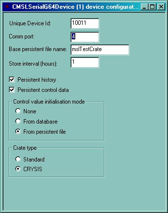
MSL G64 device, Serial crate version:
Unique device id: The unique device id as defined in the database, DeviceLocation table.
Comm port: The windows serial port where the crate is attached.
Base persistent file name: If at least one of 'Persistent History' or 'Persistent control data' is checked the base file name must be specified. The filename should be specified without path and extensions. It is used to generate the persistent files used to store current control data and history data. The data files are stored in the ConSys executable directory. The extension on history files is 'hst' and on control files 'permanent'. See also the description of the initialisation method below.
Store interval (hours): The time between update of the persistent data on disc. Under normal conditions, the persistent data is stored when the control system is closed. To ensure loss of data in case of a crash the persistent data is updated regularly at the specified intervals.
Persistent history: Checked, if histories should be stored to disc.
Persistent control data: Checked, if control values should be stored to disc.
Control value initialisation mode:
None: The control values are not transferred to the G64 crate
during initialisation
From database: The control values is obtained from the database
default values and send to all control values in the G64 crate.
From persistent file: During device initialisation the
device first looks for a file with the name '<Base persistent file name>.loadOnce'.
If this file exist the command values are loaded from the file and the file is
deleted. If the file does not exist, the device looks for a file with the name
' <Base persistent file name>.permanent' and load
the command values from this file. If no file could be found the default values
from the database is used to set the crate control values.
Crate type:
Standard: Standard G64 serial crate.
CRYSIS: Crate with special functionality for the table driven CRYSIS
G64.
MSL G64 device, Camac crate version:
Almost like serial version.
CAEN
Device:
Under development.
MSL
GFD/Timing system:
Under development
AEG
Timer and event decoder device:
Device to handle the AEG (Autonomous Event Generator) module and the event decoder module.
Status and control of the device - address type: One dimensional addressing (9):
|
Parameter |
Suggested |
Description |
Data Type |
Interpretation |
Mode |
Comment
|
| 1 | lStatus | Status of the load | Bit | Status bit | Read | True when a table is being loaded |
| 2 | lastLoad | Status of the last load | Bit | Status bit | Read | True if the last table load was successfull. |
| 3 | cntOk | Counts succesfuld loads | Word | Word | Read |
|
| 4 | cntFail | Count number of failed load | Word | Word | Read | |
| 5 | DataValid | Last data block was valid | Bit | Status bit | Read | |
| 6 | ResetCnt | Reset counters | Bit | Pulse bit | Write | |
| 7 | cntIdent | Count identical data | Word | Word | Read | Counts the number of data blocks that where identical to previous load and therefore not transmitted to hardware |
| 8 | skipIdent | Skip loading of data identical to previous data | Bit | Check box | Write |
Table data: CAMAC Timing Event address (31)
|
CAMAC C |
CAMAC N |
Table type |
Table layout |
| 1..14 | 1..23 |
0: AEG Timing table |
AEG Timer data layout: 256..511: Seconds and milliseconds: Must be <= 59999. 512: Table size, 0 => 256 (full table) |
| 1..14 | 1..23 | 1: Event decoder |
Event decoder data layout: 0..<size-1>: Event table, max size is 256 Each event having the following format: B0-B2: Output number. This output will be pulsed if enabled. B7: Enable |
GFD Device:
Device to handle the GFD/GOCT.
Status and control of the device - address type: One dimensional addressing (9):
|
Parameter |
Suggested |
Description |
Data Type |
Interpretation |
Mode |
Comment
|
| 1 | lStatus | Status of the load | Bit | Status bit | Read | True when a table is being loaded |
| 2 | lastLoad | Status of the last load | Bit | Status bit | Read | True if the last table load was successfull. |
| 3 | cntOk | Counts succesfuld loads | Word | Word | Read |
|
| 4 | cntFail | Count number of failed load | Word | Word | Read | |
| 5 | dataValid | Last data block was valid | Bit | Status bit | Read | |
| 6 | resetCnt | Reset counters | Bit | Pulse bit | Write | |
| 7 | cntIdent | Count identical data | Word | Word | Read | Counts the number of data blocks that where identical to previous load and therefore not transmitted to hardware |
| 8 | skipIdent | Skip loading of data identical to previous data | Bit | Check box | Write |
Status and control of the device - address type: CAMAC C-N address (33)
|
CAMAC C (a0) |
CAMAC N (a1) |
Suggested SurName |
Description | Data Type | Interpretation | Mode |
| 1..14 | 1..23 | resetModule | Reset GOCT module | Bit | Pulse bit | Write |
GFD Table data: CAMAC_GFD_ADR (32)
|
CAMAC C |
CAMAC N |
GFD channel number in GOCT |
GFD table number (a5) |
Table layout |
| 1..14 | 1..23 |
0..7 |
0..7 |
Table with up to 128 vectors 0: Absolute start value |
Last Modified 06 May 2020